VMC – vSAN ESA
Table of Contents
vSAN Express Storage Architecture (ESA) was announced at VMware Explore last year (2022) and while it’s been available for our on-premise customers for nearly a year it hasn’t been available in VMC until now…. With the release of the M24 version of VMC. It is now an option for newly provisioned SDDC’s
So why is this such an important change? to answer that we need a history lesson on vSAN

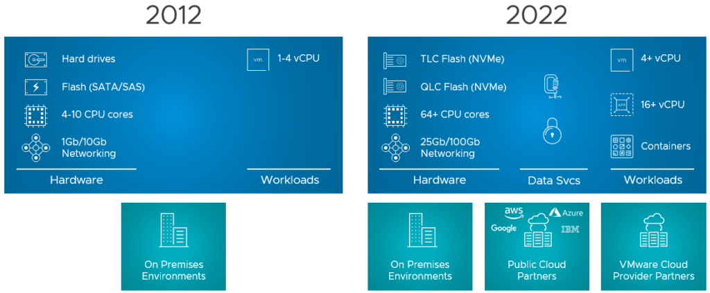
vSAN first came to market in 2014, and the typical hardware of the day from a storage perspective was dominated by spindles. Flash had arrived on the scene but was VERY expensive and datacenter networking was in the transition from 1Gb/s to 10Gb/s. As a result of this and other factors design decisions were made in the original vSAN (referred to here as OSA) to implement a tiered storage architecture. This was made up of flash-based cache drives and flash or hard disk-based capacity drives. These were then combined into something called a disk group. This decision led to several consequences.
The first is that the cache drive cannot be used for storing data it is only a transient write buffer. As all writes go to the cache drive in a disk group in some circumstances this could limit the peak I/O available.
It also meant that the endurance of this drive was paramount. This was a challenge in the early days of flash drives.
To improve performance and reduce failure domains it’s possible to have multiple disk groups within a host. This is something that we implement in VMC using vSAN OSA this further compounds the reduction in usable storage. as multiple drives are allocated to the cache role.
As All-Flash has now become the normality it was worth revisiting the architecture.
To understand more about the under-the-hood architecture of vSAN see the official overview
vSAN ESA – Benefits
Putting all of the above changes together brings significant benefits to VMC customers when using the ESA version of vSAN.
Performance benefits
- Significant increase in available IOPS ( all drives are used for reading and writing)
- Adaptive write path for maximum throughput (Especially relevant for customers that require high throughput on a single or low number of VMDK’s)
- Improved snapshot mechanisms reduce the impact on the guest workload (Snapshot deletion is up to 100x faster combined with much reduced primary latency when running workloads from snapshots. As business demands lower RPO’s any improvement in snapshot mechanisms reduce the overhead to the guest workload.
Efficiency benefits
- Improved compression algorithms for better data reduction
- More efficient compression algorithms free up the Host CPU for Guest OS processing
- Reduced storage network traffic (compression happens on the source host and then all replication is already compressed)
- further enhancements reduce the CPU overhead when using vSAN Encryption (This is always used in VMC)
- Always on UNMAP/Trim (This helps to free up unused blocks at the Nand block level)
- The ability to deploy a parity-based (RAID5) with 3 Nodes. (OSA requires a minimum of 4)
- The performance of the parity-based (RAID5/6) of the ESA implementation now exceeds the RAID1 performance of OSA. Customers can get increase savings by changing the storage policy.
Resilience Benefits
- less rewrites in the event of a device replacement – Although this is a significant benefit for on-premise customers with VMC if we have a drive failure we will replace the entire node.
vSAN will only be available on the i4.metal-based VMC hosts at launch. It is also not currently available in a 2-node or Stretched SDDC configuration
Sizing
As part of my job in VMware Cloud Pre-Sales a critical aspect is sizing VMC solutions for customers. This is usually done as a first pass with RVtools inputs into our sizing tools.
But what does that mean to a customer?
My colleague Nikolay put together this handy table. This is assuming a conservative compression ratio of 1.25% for ESA. The reality is we expect this to be higher.
| Nodes | OSA (Compression 1.25) Policy In use | Capacity (TiB) | ESA (Compression 1.25) Policy In use | Capacity (TiB) | Delta % |
|---|---|---|---|---|---|
| 2 | FTT1, Mirror | 14.09 | N/A | N/A | N/A |
| 3 | FTT1, Mirror | 23.5 | FTT1, RAID5 | 37.22 | 58.38 |
| 4 | FTT1, RAID5 | 51.87 | FTT1, RAID5 | 51.21 | -1.27* |
| 5 | FTT1, RAID5 | 66.03 | FTT1, RAID5 | 65.19 | -1.27* |
| 6 | FTT2, RAID6 | 70.56 | FTT2, RAID6 | 79.18 | 12.22 |
| 7 | FTT2, RAID6 | 83.11 | FTT2, RAID6 | 93.16 | 12.09 |
| 8 | FTT2, RAID6 | 95.65 | FTT2, RAID6 | 107.15 | 12.02 |
| 9 | FTT2, RAID6 | 108.2 | FTT2, RAID6 | 121.13 | 11.95 |
| 10 | FTT2, RAID6 | 120.75 | FTT2, RAID6 | 135.12 | 11.90 |
| 11 | FTT2, RAID6 | 133.3 | FTT2, RAID6 | 149.1 | 11.85 |
| 12 | FTT2, RAID6 | 145.85 | FTT2, RAID6 | 163.09 | 11.82 |
| 13 | FTT2, RAID6 | 158.4 | FTT2, RAID6 | 177.08 | 11.79 |
| 14 | FTT2, RAID6 | 170.95 | FTT2, RAID6 | 191.06 | 11.76 |
| 15 | FTT2, RAID6 | 183.5 | FTT2, RAID6 | 205.05 | 11.74 |
| 16 | FTT2, RAID6 | 196.04 | FTT2, RAID6 | 219.03 | 11.73 |
*As ESA has a dynamic parity-based mechanism it can either use 2+1 or 4+1 however OSA has the capability of using 3+1. This is why the 4 and 5 node has a lower usable space.
The above table is the usable capacity for workloads including the management objects. Additional clusters would have more space.


